Before the launch in handling I/O GPIO of Raspberry, it is preferable to design a small circuit board that will prevent your lovely raspberry makes the soul in mishandling.
That is why it is important to protect the GPIO.
For information, you have a total of 17 GPIO on the Raspberry PI.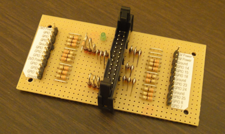
GPIO
Source : Wiki Raspberry PI
Principle of protection of GPIOs
To prevent entry of Raspberry Pi being subjected to a voltage higher than the recommended max 3.3V
We will make this little montage of each GPIO Raspberry Pi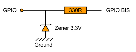
materials needed
Here is the list of materials needed :
- A soldering iron (with the sponge is better ^ ^)
- Welding wire (tin)
- Tools (cutting pliers, etc ...)
- Bakelite plate test (http://wak.li/1qg)
- 18 Resistors 330 Ohms (http://wak.li/1qh)
- LED as a activity indicator (http://wak.li/1qi)
- 17 Zener 3.3v (http://wak.li/1qj)
- 2 IDC female connectors 26 pin (2x13) (http://wak.li/1qk)
- 1 sheet 26 drivers (http://wak.li/1ql)
- 1 IDC connector male 26 pin (2x13) (http://wak.li/1qm)
- PCB terminal blocks for a minimum of 20 terminals
IDC connectors
The purpose of this manipulation is to have a tablecloth that easily connect to the GPIO of Raspberry PI.
This sheet will serve as a liaison between GPIO and card protection.
As a first step: cut the length you need.
20 cm seems to me a reasonable length.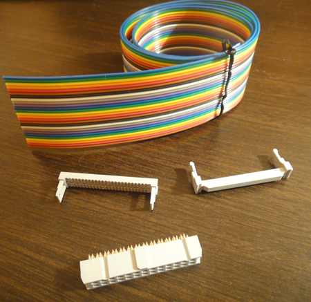
Then you should crimp IDC connectors on the cable.
Insert on the tablecloth then tightened correctly, for that I suggest you a vise or clamp.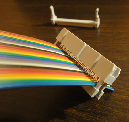
And final result (with a nice faux-fitting ^^)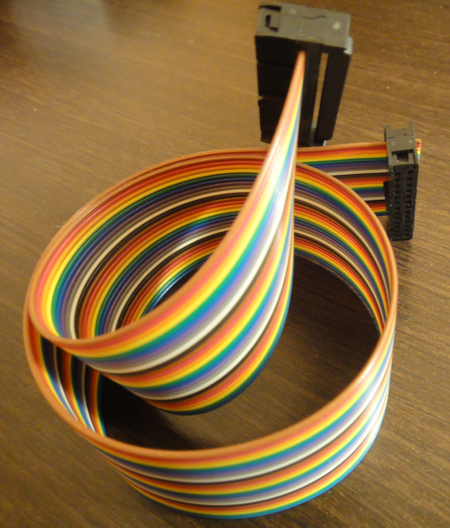
Card design
Mounting : 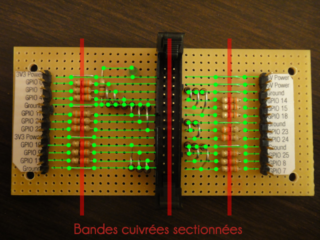
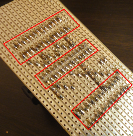
And here is the card once welded correctly.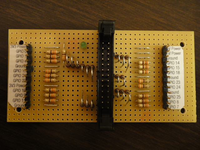
Of course, depending on the type of test that you purchase you will have to adapt it to match your expectations card.
And for some cards (copper bands), armed with a knife, you cut some tracks.